Kate Malmsbury


PATH TO SUCCESS
We walked first try on the ground!
The Klann leg lengths we chose to implement took a while to perfect. The first way I worked on them was using complex calculations and paths found in several extremely technical documents online. The foot path created by those lengths did not have a smooth flat bottom, far from ideal. Thanks to the website linked below there was an easier way to simulate the leg mechanism and change the leg lengths and see the generated path. Further issues appeared after using the second iteration of leg lengths because the thickness of the legs, made of real material, interfered with the motion of the leg. The simulation legs were lines with no thickness. With these past mistakes in mind, I used the simulation to generate a good leg path keeping potential interference zones in mind. From there I created the links in CREO and traced the path with that software to see if the path matched the simulation and also to make sure that there were no interference issues. From there I modeled the simulation using our link lengths and leg mechanism working form the Matlab script template given to us by our TA Brian McGuigan. The Matlab results are displayed more in depth on the corresponding page.
https://dogfeatherdesign.com/engineering-projects/mechanisms-mechanical-walker/
Matlab - CREO - Online Simulation
LEG PATH

MATLAB

CREO PARAMETRIC

ONLINE SIMULATION
All work done by me, Kate Malmsbury
Matlab: PVA - DFA
LEG MOVEMENT ANALYSIS
The position velocity and position (PVA) and dynamic force analysis (DFA) was completed using the code template created by the TA, Brian McGuigan. The first set of data is using a simulation where the foot of the leg was moving and the motor was constrained. The second set uses a simulation that constrains the foot at one point and lets the motor move around. Unfortunately data from that set was not accurate due to an error in the template (and not an error due to the code I wrote.)
We took into consideration the gravity force on the walker/automaton body by assuming that the weight is equally divided by the number of ground contact points (1. See point )
We did not consider the 3-D torque acting on the the legs; We assumed they were 2-D Objects
We assumed that the chassis (holding the motor) does not rotate and that is stationary with feet only seeing force on contact with the ground
With the stationary foot: We assumed that the chassis (holding the motor) does not rotate: it is constrained to move in the horizontal direction and vertical direction as if constrained by frictionless sliders.
We are assuming the robot is being lifted by one ground contact point on one foot as we have added the automaton weight to Link 10.
PVA
These analysis are based off a crank velocity of 720 deg/sec based off an estimate taken from a video of our actual automaton/walker walking on linoleum floor.
DFA
These analysis are based off a measured automaton weight and calculated weight totals to 1.5473kg. This converts to 15.174N.
Due to using the moving foot simulation assumption force and torque values are only relevant between crank angle 98deg - 300deg when the foot is making contact with the ground.

MATLAB SIMULATION
...

FOOT PATH
Height and a flat bottom are important for the foot path.
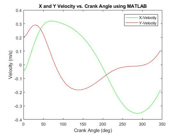
X AND Y VELOCITY OF THE FOOT
...
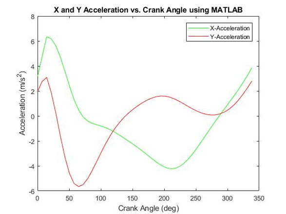
X AND Y ACCELERATION OF THE FOOT
...
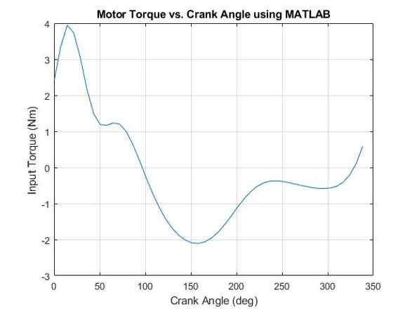
MOTOR TORQUE GRAPH
The max torque magnitude is around 2Nm which is expected. Removing the lid from a new jar is about 4-6Nm and we expect the torque our motor has to handle (on linoleum) around half this based on its total weight.

X FORCE ON LINK 12 AT NODE 4 GRAPH
The X Force was expected to be much less than the Y Force because the Y Force incorporates lifting the weight of the automaton and the X Force does not.

Y FORCE GRAPH ON LINK 12 AT NODE 4
The max Y Force magnitude within our range is around 16.9N which is exactly around
what we would expect given that our total automaton/walker weight is around 15.74N and
the Y Force must include lifting the entire automaton/walker weight.

FIXED FOOT MODEL - MATLAB SIMULATION
I spent too much time trying to fix this so that the PVA and DFA ran successfully to no avail.
All PVA and DFA and corresponding graphs created by Kate Malmsbury using the template code made by TA, Brian McGuigan