KATE MALMSBURY'S PORTFOLIO
FORMULA SAE
Engine Subteam and Project Lead on Drivetrain Subteam
Aug. 2015 - Present
CAD - CREO; FEA - Ansys; Graphing - Matlab, Excel
I have been a member of University of Illinois' Formula SAE team, the Illini, Motorsports, since my freshman year, Fall 2015. This involvement has provided many engineering challenges, team work, and is overall the greatest learning experience of my college career. I have been able to design components for the car, extrapolate from previous projects, fabricate/machine parts used on the car, and even create my own projects furthering my knowledge and experience.

PRODUCT
Customer Favorite
This is your Product description. Write a short overview including important features, pricing and any other relevant info for a potential buyer. Consider adding an image or video that shows off your great-looking product and entices users to make a purchase.
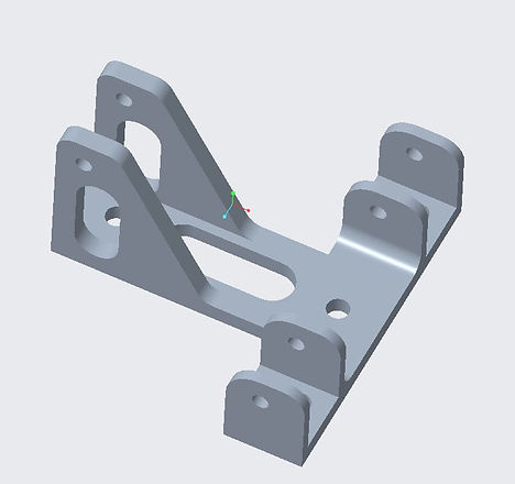
PEDAL BOX
Project Design Lead
This project centered around the braking system for the 2018/2019 Formula SAE vehicle. The formula car uses a hydraulic braking system which converts kinetic energy into thermal energy, safely slowing the vehicle down. Last year, the pedal and pedal box design were criticized for being under-engineered and lacking ergonomic features. This design of the brake pedal and pedal box setup is optimized for safety, minimal weight, and driver comfort. These factors were determined based on weight transfer calculations on the tires, calculated foot-force on the pedal, geometric constraints within the car, estimated height, weight, and foot size range of the drivers. The design follows the competition rules, specifically the one that states that the pedal must be able to withstand a force of 2000 Newtons.
This project included multiple calculations to determine the pedal geometry. The positioning for the master cylinders, pedal, and the pedal length had to be determined based on the needed mechanical advantage. To determine the locking pressure calculations had to take into account simple mechanical force body diagrams and incorporate aerodynamic influence, tire influence, and sizing factors.
Following the brake geometry calculations, a detailed design matrix was created to determine the best top plate and base plate designs to minimize weight and increase driver comfort. Each design was modeled in CREO and FEA (Finite Element Analysis) was used to test the stress on each design. Other aspects of this design process include bolt sizing calculations, pedal improvements, and the corresponding manufacturing.
This project is summarized with detailed images in the document attached below.

SILENCER DESIGN
7 Tube Design from 4 Tube Design
The exhaust system consists of the headers, tertiary, muffler, and silencer. The purpose of this system is to expel exhaust gases from the engine efficiently. The current 7 tube design reduces the effective exhaust area from 3.1415 in2 to 0.77312 in^2 compared to the old 4 tube design that reduced area to 0.44178 in^2. This takes the least amount of power from the engine, while also passing the required sound test for competition. This project consisted of research and design on the silencer. The silencer is mounted within the muffler, and consists of several tubes of varying length mounted longitudinally. The 7 tube silencer, along with a specific tune helped us pass sound without the need for supplementary muffler packing. (110 dBC at 11500 RPM, 103 dBC at idle).
.
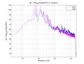
AEROACOUSTIC OUTPUT
My Own Project
I created this project myself when I was a freshman with little engineering experience. I worked with Professor Errede to study the output from the engine. The old 4 tube silencer was added to look at the difference in output with and without the silencer. Looking at the graph on the right, the blue line is with the silencer, the pink is without. These graphs were used when looking at the 7-tube redesign described above.
BUSINESS PLAN
Top 3 for the Last 3 Years
I have studied automotive market trends to assist with the team's business plan which is a portion of the Formula SAE competition. The data and research that I have contributed has been included in our business presentations for the past three years. Over these three years we have consistently placed in one of the top three slots at competition.

OTHER
GT Power
Machining
Some of the other projects that I have assisted with include GT Power simulations and machining projects.
GT Power:
GT-Power simulates various properties of combustion (Power, Torque, efficiency etc) and fluids (Velocity, temperatures, pressure) by using fluid mechanic equations. It solves these equations for every small length ( specific length which you enter) and does this throughout an intake model to calculate all those properties at different points in the system.
Machining Projects:
Mill Blocks (Mill)
Spacers (aluminum rod stock) – (Lathe) turning, facing, and parting