KATE MALMSBURY'S PORTFOLIO

MECHANICAL ENGINEERING 370 AUTOMATON
INTRODUCING THE REAL SUPER MARIO
Spring 2018
CAD - CREO
Coding - Matlab
ME 370
Mechanical Engineering Design
The class objective was to build an automaton atop a walker. The automaton had to include either a cam shaft or gear train and also needed to include a linkage mechanism. The walking aspect had to have legs driven by the motor. Wheels were allowed but they could not be driven by the motor.
I was the project leader for this main junior design project. The work described below is all my own individual contribution to the project unless otherwise noted.
THE REAL SUPER MARIO AUTOMATON
A Walking Automaton
I bring you the reinvention of the Super Mario Bros Game. My team has incorporated the use of shafts, cams, a linkage mechanism, and a gear train. When the motor is switched on, the cams move Mario and his friends up and down. The linkage mechanism converts rotational motion to translational motion, which causes the coins our characters are trying to catch, to move in and out of their reach. The motor also drives the legs moving the automation forward through the use of a gear train and based on the Klann leg mechanism design.
Our team's goal was to capture attention with a complex yet comprehensible automaton design while simultaneously challenging our engineering design skills and impressing our professor. We believe children who want to learn about engineering principles tend to gravitate towards vibrant, interactive, and relatable exhibits over information-dense presentations.
Please enjoy our infomercial themed video presentation below.


Demonstrating to kids at EOH
IDEATION
Building an Idea
The initial steps of this design process had our group thinking about who our user group was and what their needs and wants were. As seen in the gallery to the left, we used brainstorming techniques to help map out our thinking. First we thought individually, then we joined together to discuss ideas. I wanted to focus on kids at Engineering Open House, where our rough prototype would be presented. From there, our group discussed what age we would be targeting. We eventually decided on middle school aged kids. After interviewing kids who visited previous EOH and other engineering exhibitions, and other research, we concluded that kids of the middle school age tend to gravitate towards vibrant, interactive, and relatable exhibitions. We thought a Mario themed presentation would fit the bill nicely because it is so universal!

LOW-FI ROUGH PROTOTYPE
Super Mario Comes to Life
During this stage in the design process we were taking our ideas from the ideation process and making them come to fruition. We were making an automaton (mechanical device) out of low quality materials to test how our design ideas worked; from paper to real world application. As mentioned in the About page, this model had to have a cam shaft or gear box and a linkage mechanism. We used rotating cams, as can be seen below the green pipes that Mario and friends jump out of.


PATH TO SUCCESS
We walked on our first try on the ground!
The Klann leg lengths we chose to implement took a while to perfect. The first way I worked on them was using complex calculations and paths found in several extremely technical documents online. The foot path created by those lengths did not have a smooth flat bottom, far from ideal. Thanks to the website linked below there was an easier way to simulate the leg mechanism and change the leg lengths and see the generated path. Further issues appeared after using the second iteration of leg lengths because the thickness of the legs, made of real material, interfered with the motion of the leg. The simulation legs were lines with no thickness. With these past mistakes in mind, I used the simulation to generate a good leg path keeping potential interference zones in mind. From there I created the links in CREO and traced the path with that software to see if the path matched the simulation and also to make sure that there were no interference issues. From there I modeled the simulation using our link lengths and leg mechanism working form the Matlab script template given to us by our TA Brian McGuigan. The Matlab results are displayed more in depth on the corresponding page.
https://dogfeatherdesign.com/engineering-projects/mechanisms-mechanical-walker/
Matlab - CREO - Online Simulation
LEG PATH

MATLAB

CREO PARAMETRIC

ONLINE SIMULATION
All work done by me, Kate Malmsbury
Matlab: PVA - DFA
LEG MOVEMENT ANALYSIS
The position velocity and position (PVA) and dynamic force analysis (DFA) was completed using the code template created by the TA, Brian McGuigan. The first set of data is using a simulation where the foot of the leg was moving and the motor was constrained. The second set uses a simulation that constrains the foot at one point and lets the motor move around. Unfortunately data from that set was not accurate due to an error in the template (and not an error due to the code I wrote.)
We took into consideration the gravity force on the walker/automaton body by assuming that the weight is equally divided by the number of ground contact points (1. See point )
We did not consider the 3-D torque acting on the the legs; We assumed they were 2-D Objects
We assumed that the chassis (holding the motor) does not rotate and that it is stationary with feet only seeing force on contact with the ground
With the stationary foot: We assumed that the chassis (holding the motor) does not rotate: it is constrained to move in the horizontal direction and vertical direction as if constrained by frictionless sliders.
We are assuming the robot is being lifted by one ground contact point on one foot as we have added the automaton weight to Link 10.
PVA
These analyses are based on a crank velocity of 720 deg/sec, based on an estimate taken from a video of our actual automaton/walker walking on linoleum floor.
DFA
These analyses are based on a measured automaton weight and calculated weight totals to 1.5473kg. This converts to 15.174N.
Due to using the moving foot simulation, assumption force and torque values are only relevant between crank angle 98deg - 300deg when the foot is making contact with the ground.

MATLAB SIMULATION
...

FOOT PATH
Height and a flat bottom are important for the foot path.
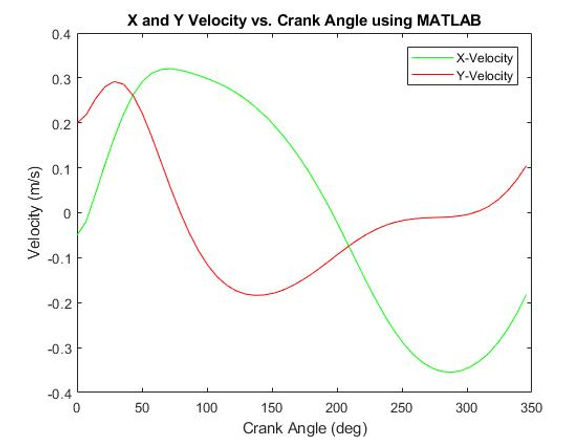
X AND Y VELOCITY OF THE FOOT
...
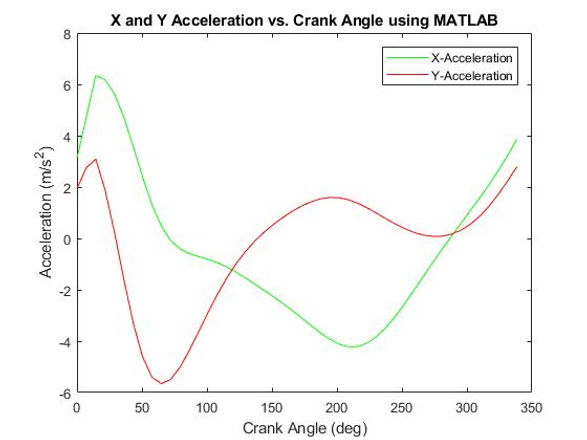
X AND Y ACCELERATION OF THE FOOT
...
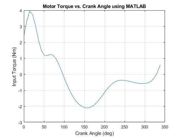
MOTOR TORQUE GRAPH
The max torque magnitude is around 2Nm which is expected. Removing the lid from a new jar is about 4-6Nm and we expect the torque our motor has to handle (on linoleum) to be around half this amount, based on its total weight.

X FORCE ON LINK 12 AT NODE 4 GRAPH
The X Force was expected to be much less than the Y Force because the Y Force incorporates lifting the weight of the automaton and the X Force does not.

Y FORCE GRAPH ON LINK 12 AT NODE 4
The max Y Force magnitude within our range is around 16.9N which is exactly around
what we would expect given that our total automaton/walker weight is around 15.74N and
the Y Force must include lifting the entire automaton/walker weight.

FIXED FOOT MODEL - MATLAB SIMULATION
I spent too much time trying to fix this so that the PVA and DFA ran successfully, to no avail.
All PVA and DFA and corresponding graphs created by Kate Malmsbury using the template code made by TA, Brian McGuigan
ENGINEERING DRAWINGS


REFLECTION
Thoughts on ME 370
This project was the most time consuming and challenging project of my college experience thus far. However, it also was the most rewarding. For the group project I was the official leader which was my first time individually leading (not including co-leading) an engineering group project. This was challenging because I was still learning concepts while I was trying to direct, lead, and teach other members of the group additional technical information. I am used to only needing social/behavioral tactics to solve group projects/problems and this needed that along with enough knowledge to explain technical information effectively to my group members. I really loved learning about the position-velocity-acceleration analysis (PVA) and the dynamic force analysis (DFA). It was especially amazing and rewarding to simulate the leg mechanisms on Matlab and be able to direct a computer to compute the analysis for you. Through learning those analyses I also improved my Matlab skills by a tenfold. I had already had previous experience with gears but little to no experience with linkage mechanisms. Degrees of freedom was a new concept to me and it was interesting to learn about it through experience, but also learn about it elsewhere in my ME340 lecture. It is always interesting to learn a concept through two different perspectives. The most challenging areas of this course were making the leg mechanism and creating the PVA code. It was difficult to get the lengths just right while making sure to accommodate for leg width, and a useable path and not have clearance issues between the different links. Paper to real life is a difficult transition. The PVA and DFA were difficult because I needed to understand PVA and DFA well and then also be able to take my knowledge and insert it into the Matlab template, a was a coding program I was not overly proficient with at the beginning of the project, using our individual leg design. Thus, I had to also learn a lot about Matlab to even understand the template code. I also learned a lot about how to work with difficult group members. This was a completely different challenge. As a leader, I had to assign people work, be supportive of the work I assigned them and also help where needed. I also had to be “the bad guy” and let people know when they were not pulling their weight. I believe though, despite those issues, that I was able to keep our group morale up even when we were one group member down. Because me and one other group member were doing the majority of the work, it was hard to make sure everything was properly time managed. There were definitely times when I could have better allocated time as a group leader. For the most part though, I think I was a good group leader in terms of making sure that good quality work got done. The most rewarding part of this project and experience was seeing our walker/automaton cross the finish line during the big race day! It was incredible to see our hard work go from a piece of paper, to a cardboard rendition, to an actual walking mechanism and to also successfully reach our goal; walking past the finish line in competition. Overall, I believe that this project helped me grow as an engineer, and I am very proud of my individual work and the team’s overall success.


